Low-Cost, Semi-Autonomous, Portable Mechanical Tester
During my fall 2018 and spring 2019 semesters at Rowan University, a fellow mechanical engineering student and I designed and fabricated a semi-autonomous, portable mechanical tester costing under $1000 with the ultimate goal marketing the device to academic institutions and small businesses. Over the course of the year, we managed to fully develop the electrical setup of the device and developed Python code to manually control the mechanical tester using a Raspberry Pi. In addition, we created a preliminary Python GUI for the device and created a custom PCB hat to use in conjunction with the Raspberry Pi. We also completely redesigned the mechanical tester in SolidWorks and fabricated the newly designed device using mills, lathes, drill presses, a laser cutter, an FDM 3D printer, and a water jet cutting machine.
Motivation
The primary motivation for this project was to develop an autonomous mechanical testing device for entities that do not have the means to purchase a multi-thousand dollar mechanical tester. To introduce K-12 students to materials science concepts, for example, a mechanical tester could be used as a teaching aid. However, purchasing a robust, multi-thousand dollar mechanical tester for educational purposes is cost-prohibitive, and the extreme accuracy and variety of features offered by industrial mechanical testers, such as long travel and programmability, is not needed if the device is to be used as an educational tool. Thus, we were tasked with continuing the development of a portable, cost-effective mechanical tester that could bring hands-on, materials science education into the classroom.
Accomplishments
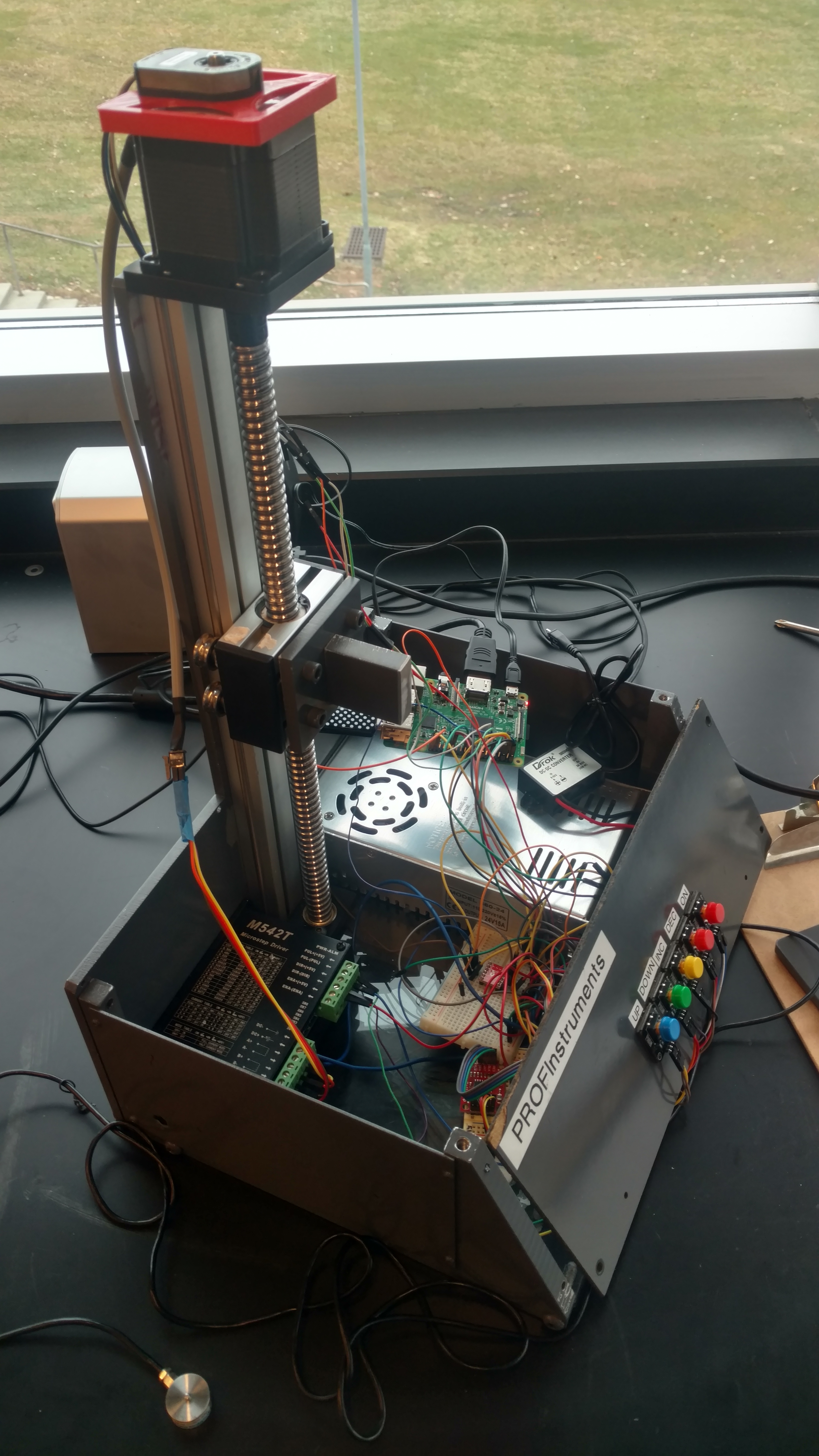
When my partner and I were first assigned to the project, the mechanical tester prototype designed in previous semesters was completely non-functional and featured a number of questionable design choices. In addition, although the device could allegedly perform tension tests in the past, a wiring diagram was never created for the device and the documentation provided by previous clinic teams was minimal at best.
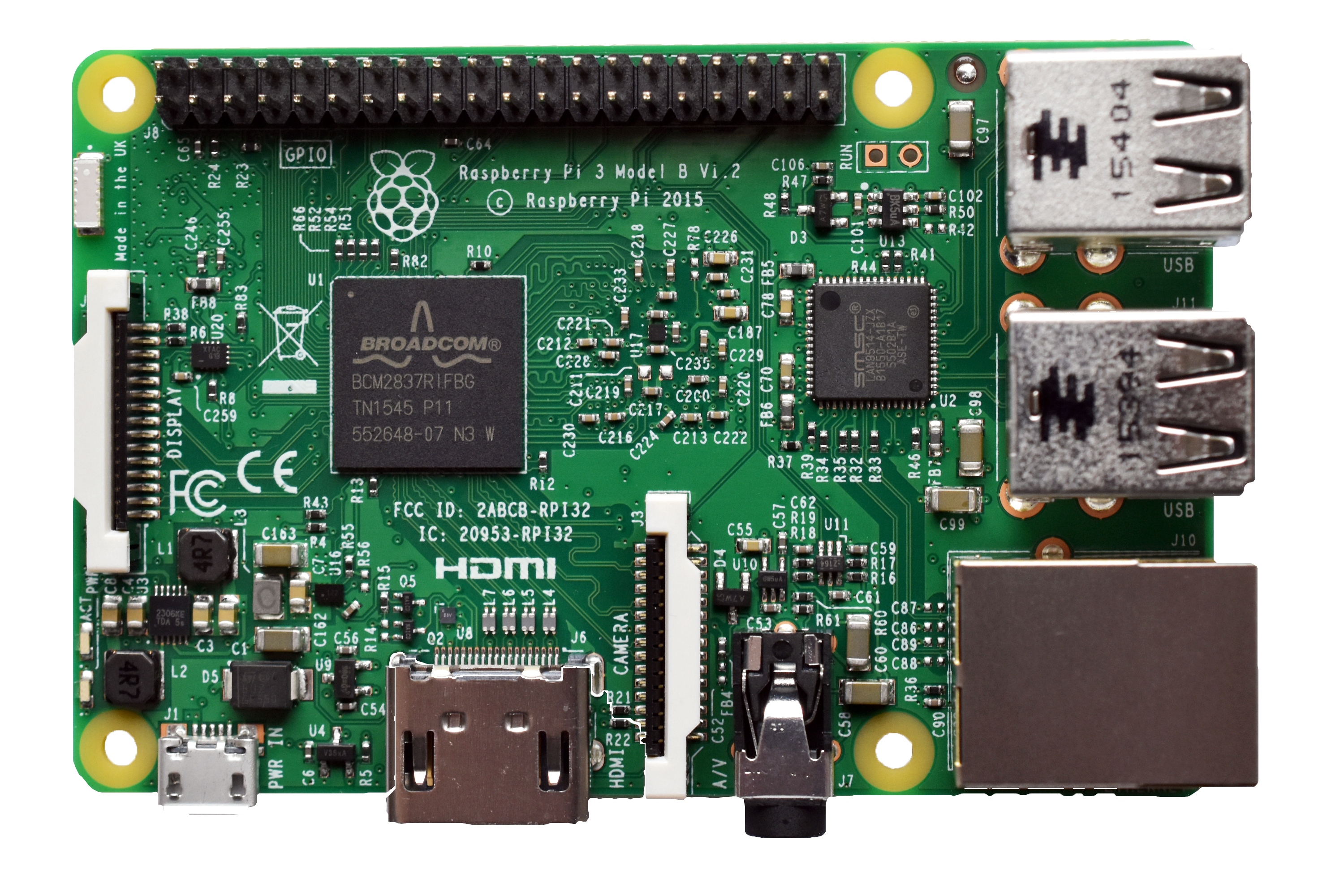
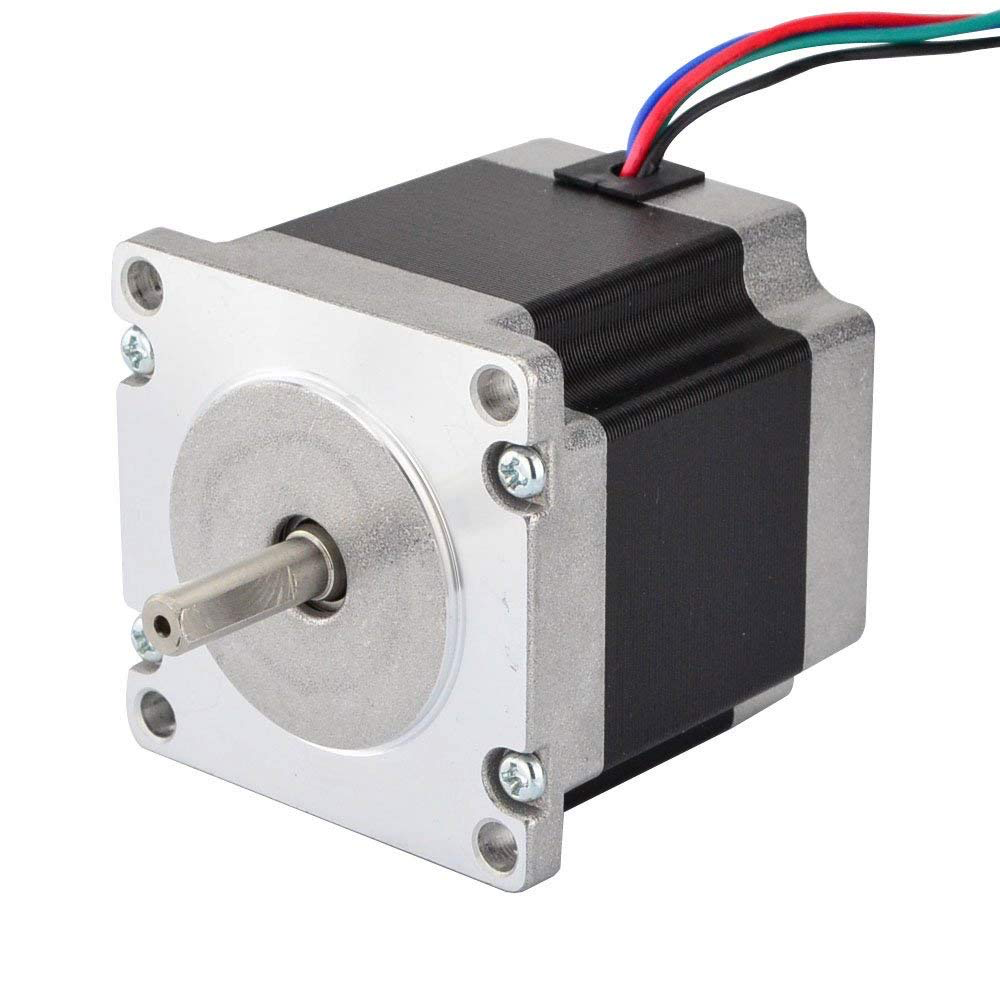
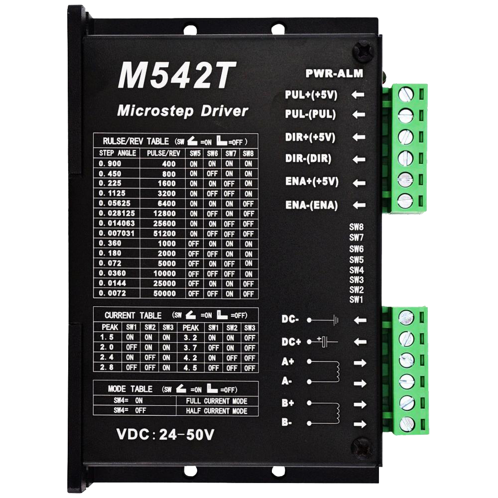
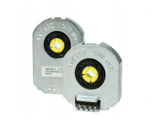
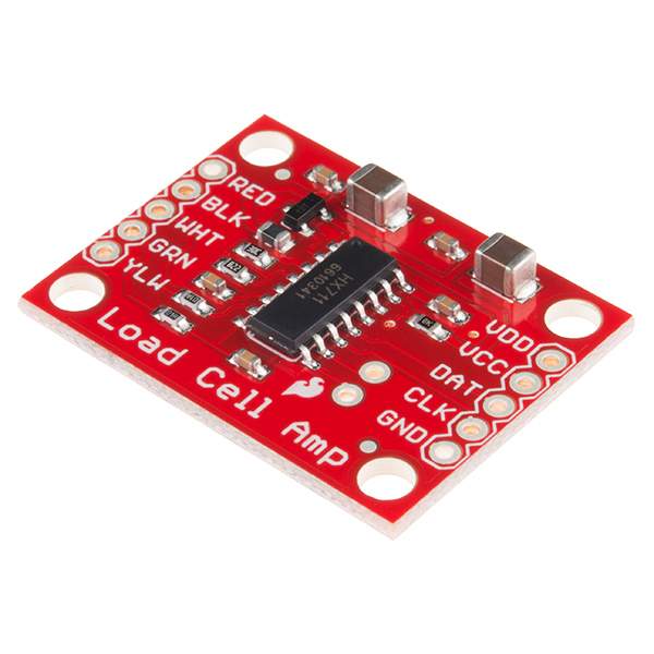
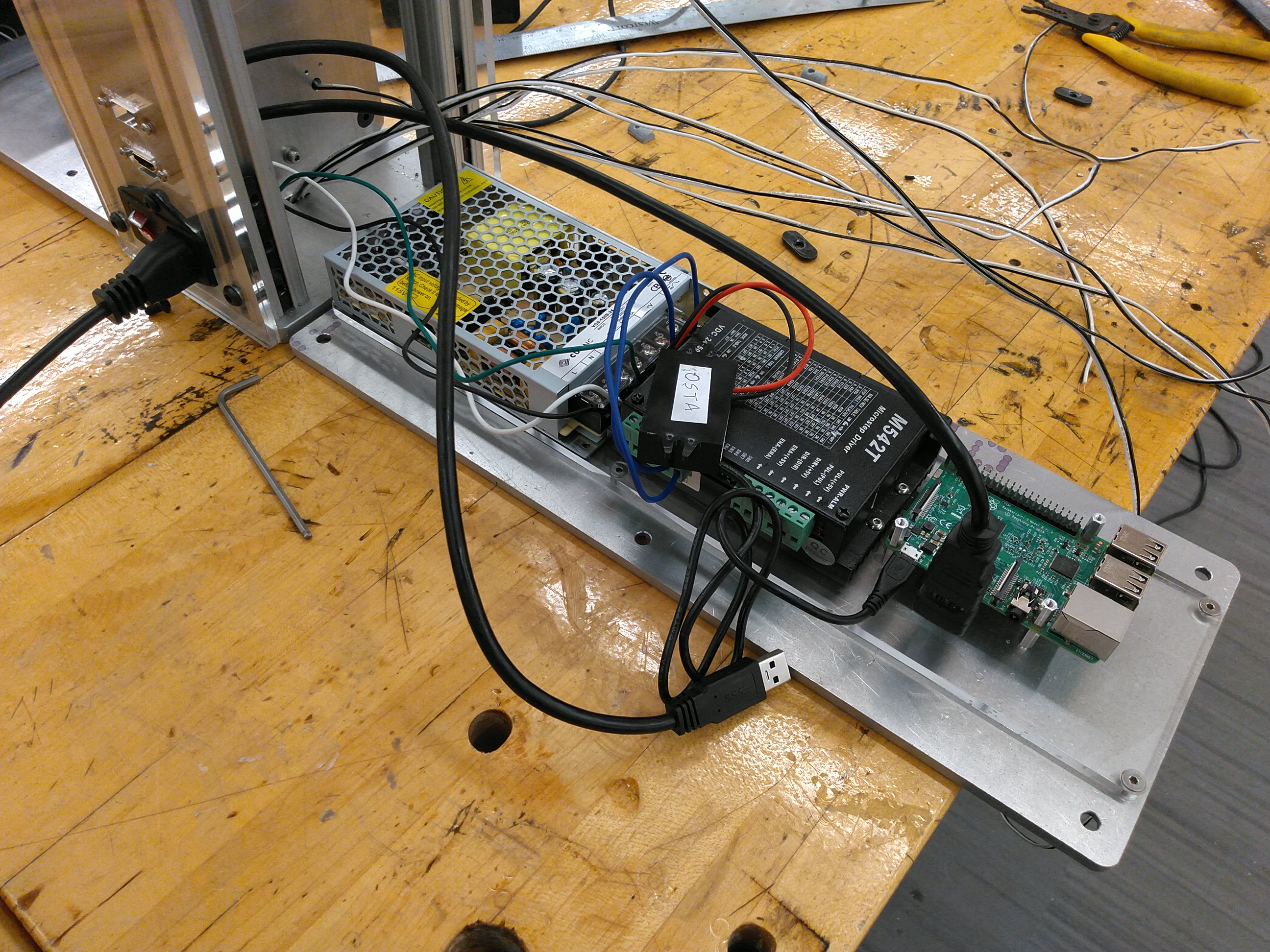
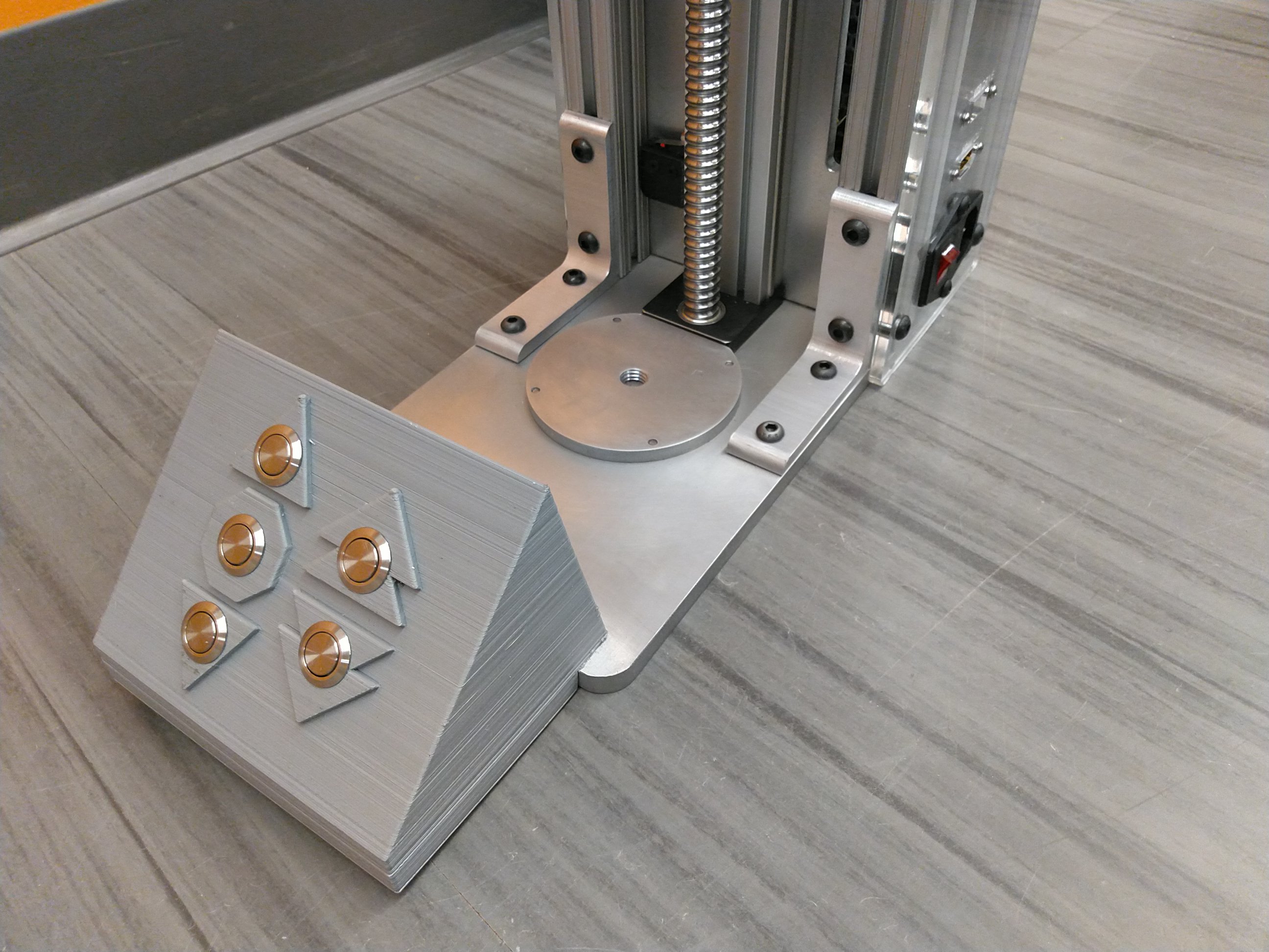
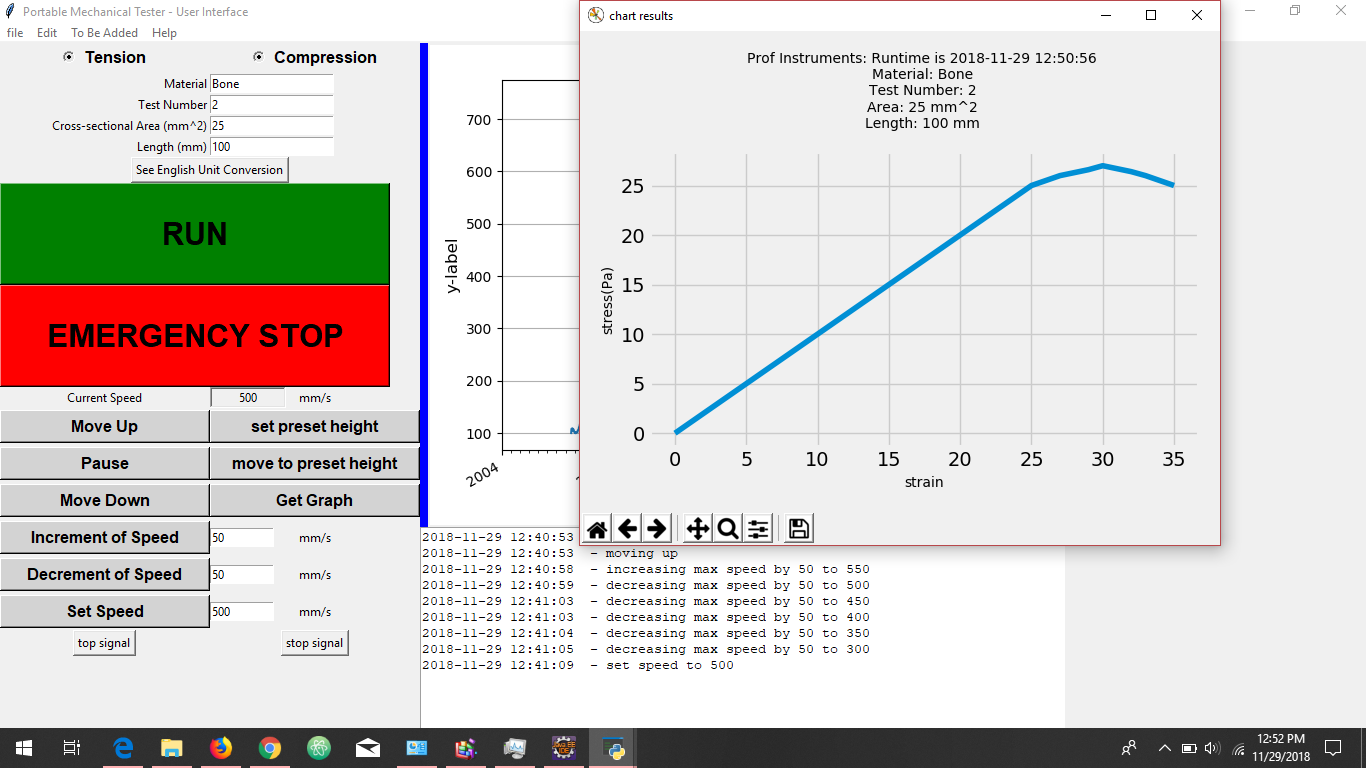
In the fall semester, my partner and I managed to successfully rewire the device using a Raspberry Pi Model B, a 24V 6.5A DC power supply, and previously sourced components, including a Nema 23 stepper motor, a M542T microstep driver, an AMT102-V rotary encoder, a SparkFun HX711 load cell amplifier, and a SparkFun 50kg compression load cell. Using Python, we implemented the ability to move up, move down, increase the speed of, decrease the speed of, and stop the stepper motor using a series of push buttons, read values from the provided load cell, and used the multiprocessing capabilities of the Raspberry Pi to run the motor and get readings from the load cell simultaneously. We also began developing a custom graphical user interface (GUI) for controlling the device using Tkinter, Python's standard GUI library.
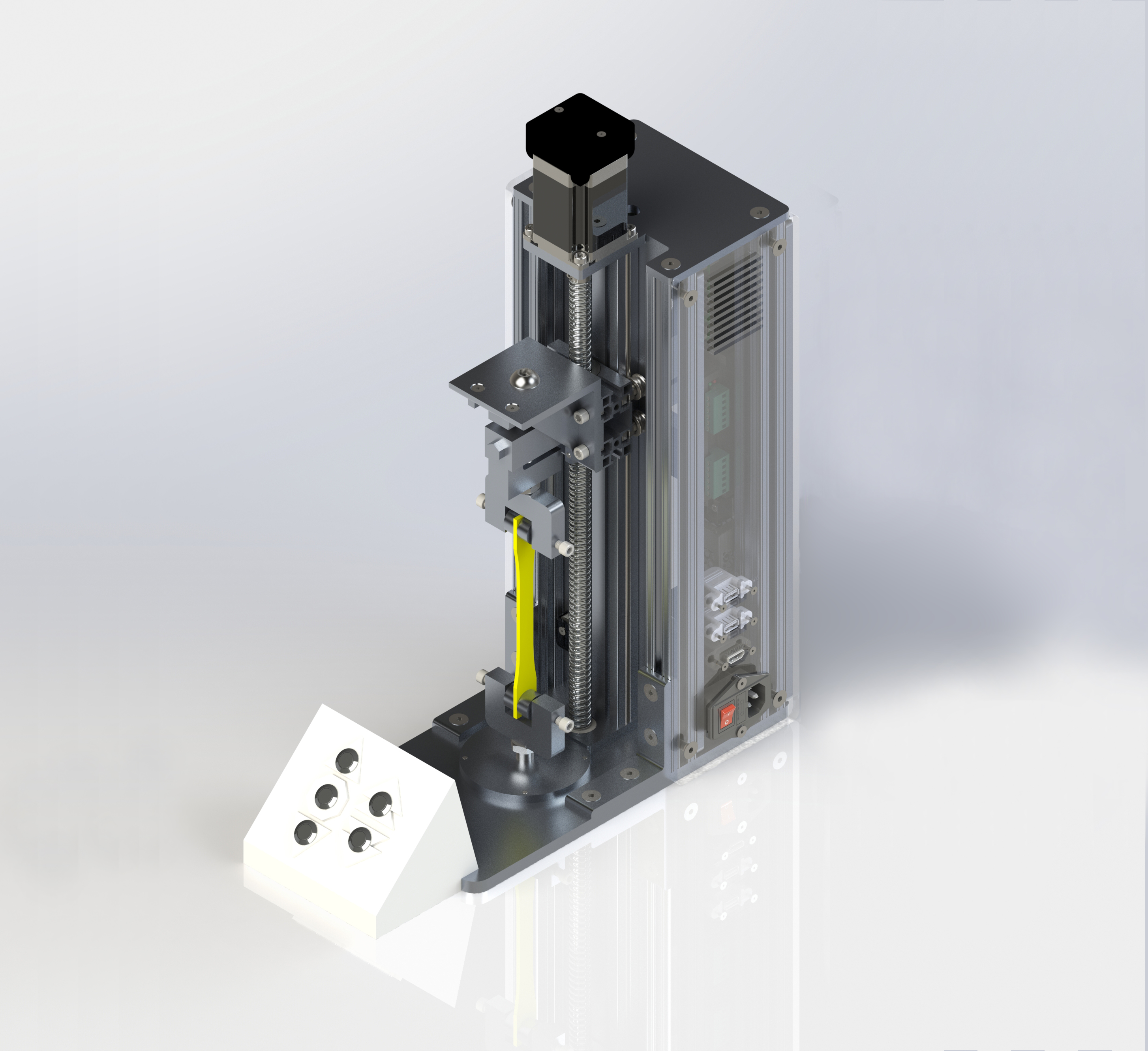
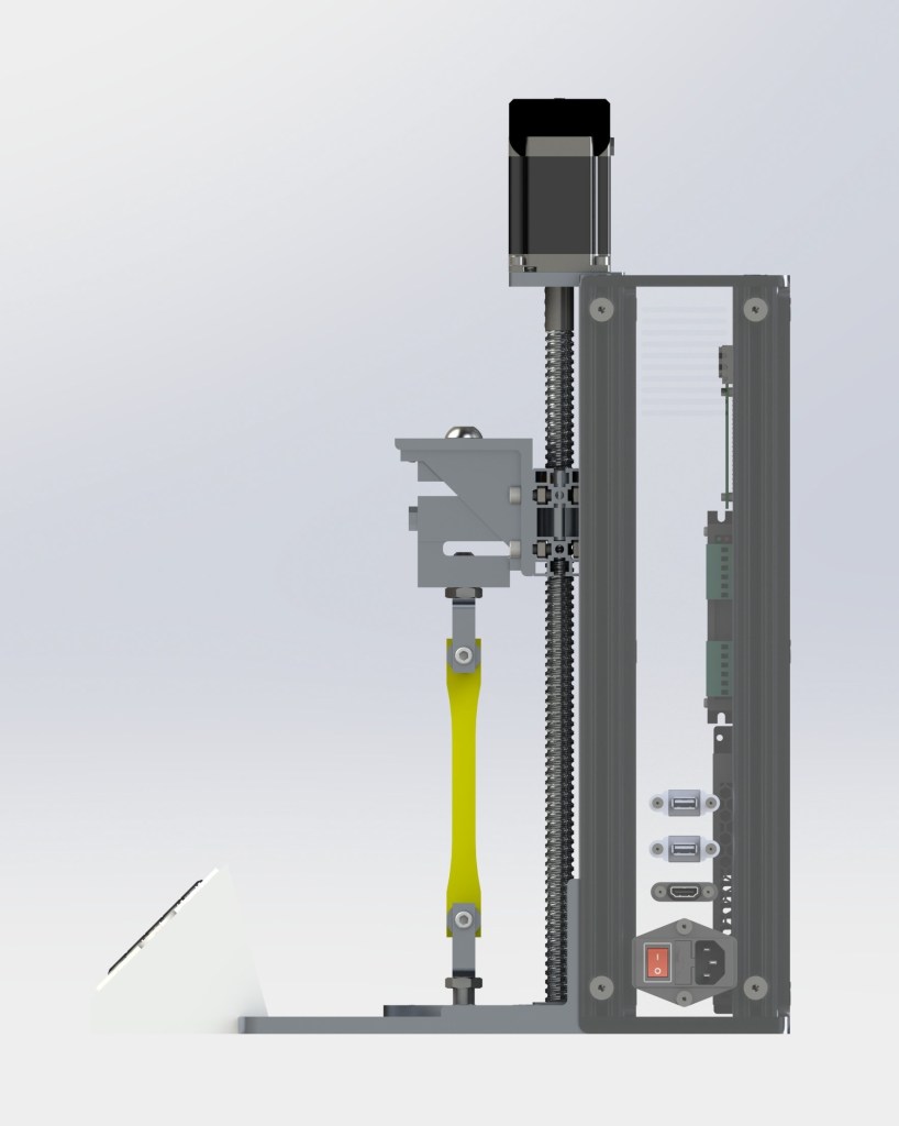
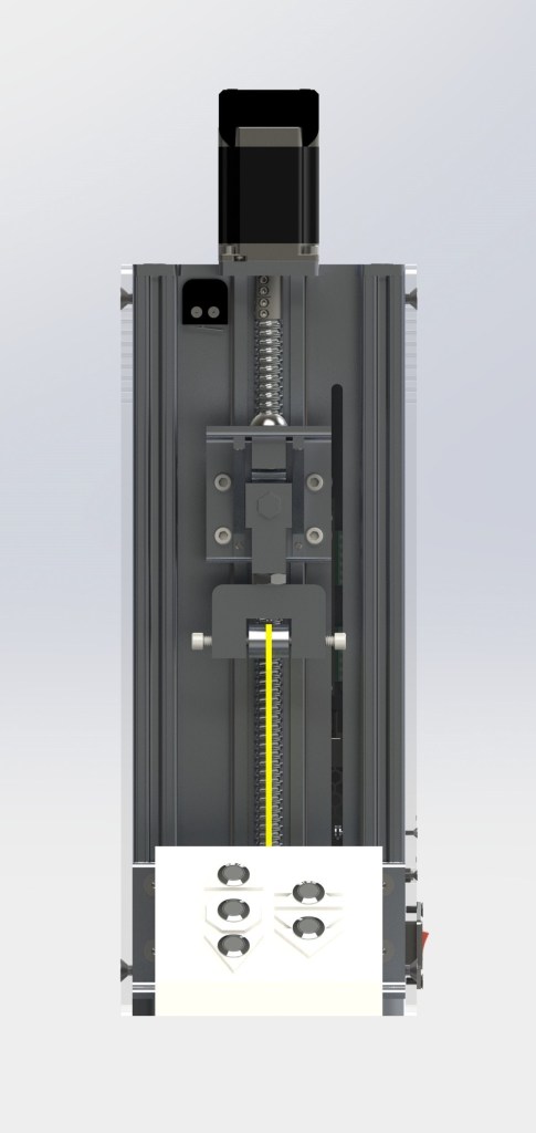
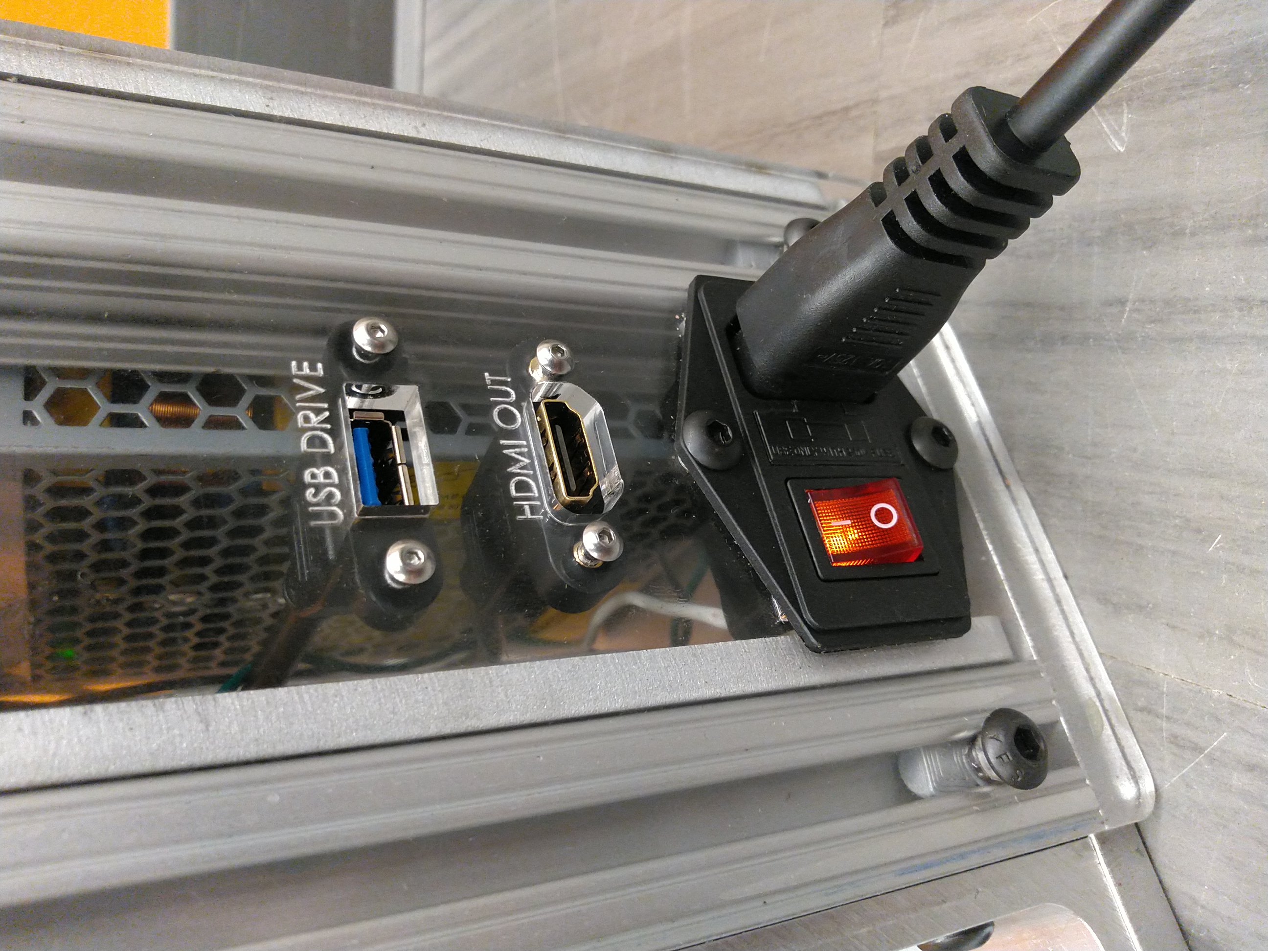
In the spring semester, we accomplished two primary goals: (1) vastly reduce the wiring complexity of our previously-developed electrical setup by creating a custom PCB shield for the Raspberry Pi and (2) redesign the device from the ground up to resolve a number of issues with the original design, such as a lack of ports for HDMI output and USB input, an absence of limit switches needed to constrain the linear actuator's vertical movement, and questionable design choices concerning the device's overall structure and aesthetics. Although we we did not end up finishing the GUI interface by the conclusion of the semester, we did manage to fabricate the newly-designed mechanical tester and partially wire the device. Unfortunately, our new load cell, an economical 500kg S-beam load cell, did not arrive in time for us to manually test the device on a basic PLA specimen, so we expect that future teams should be able to make the device fully functional by the end of the fall 2019 semester.
My Contribution
Since our team was comprised of just two individuals, there was never a time where both my partner and I had nothing to work on. While my partner developed our Python-based custom GUI over the course of the fall and spring semesters, I developed the device's electrical setup, wrote Python code to control the hardware of the device, designed the custom PCB, and redesigned the mechanical tester in SolidWorks. At the end of the spring semester, we both took part in fabricating the parts for the device using mills, lathes, drill presses, an FDM 3D printer and a water jet cutting machine.
Challenges
Since my partner and I were just a two person team, finding the time to develop the mechanical tester proved to be a constant challenge. In addition, the lack of documentation provided by previous clinic teams hindered our ability to make significant progress early on. These challenges, however, were what made the project a very rewarding experience.
Gallery
CAD Renders
Components
Raspberry Pi 3 Model B:
Nema 23 Stepper Motor:
M542T Microstep Driver:
AMT102 Rotary Encoder:
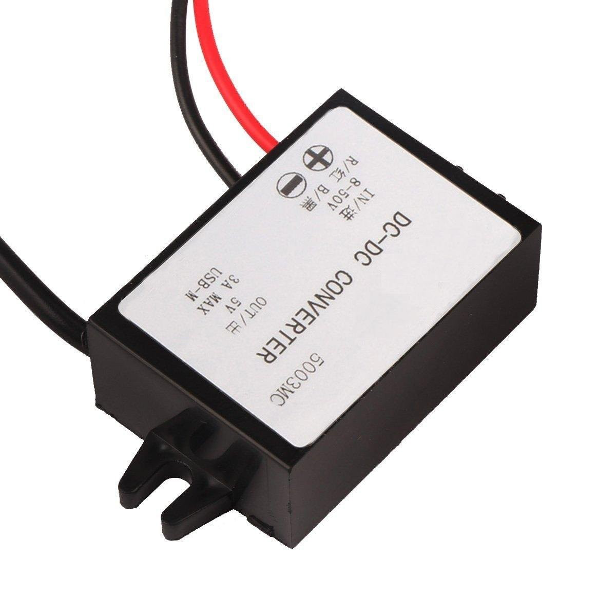
DC-DC Voltage Converter:
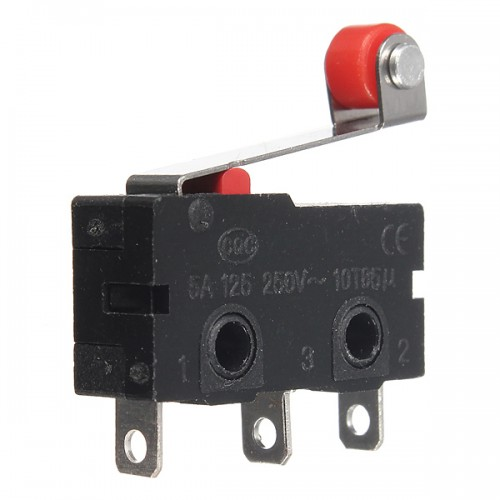
Limit Switch:
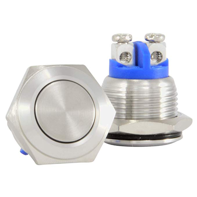
Push Button:
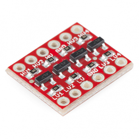
SparkFun Logic Level Converter (Bidirectional):
SparkFun Load Cell Amplifier (HX711):
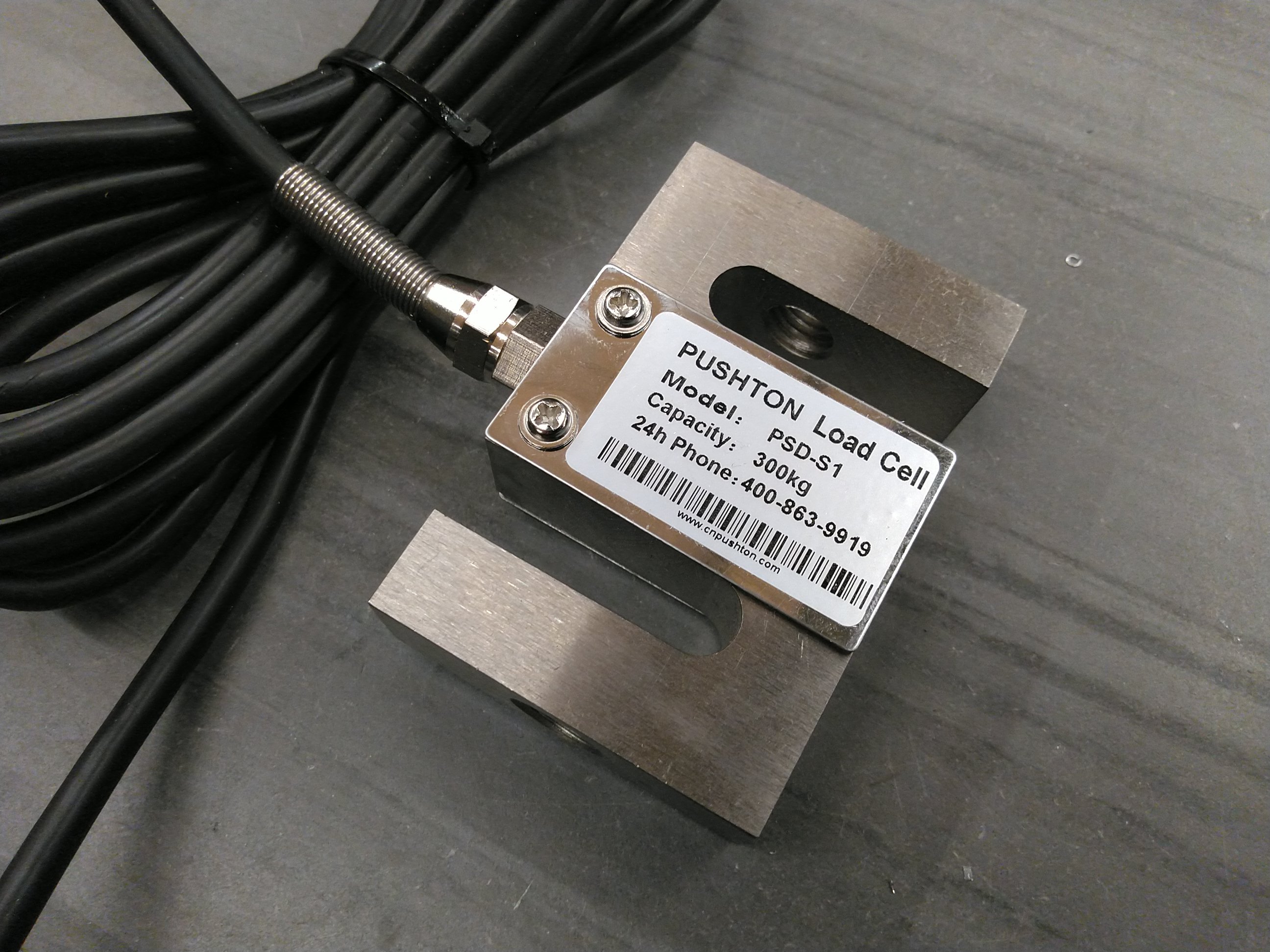
Pushton Load Cell (PSD-S1)
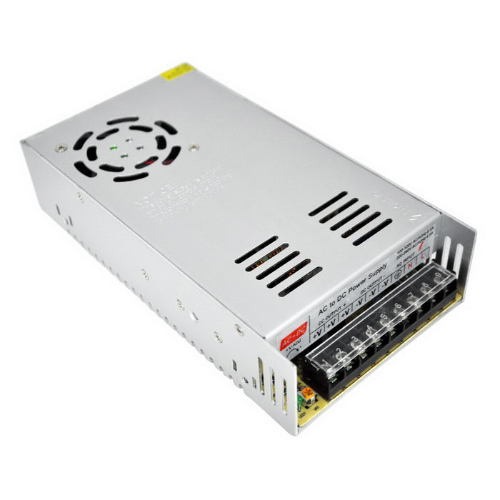
AC to DC Power Supply:
CAD Drawings
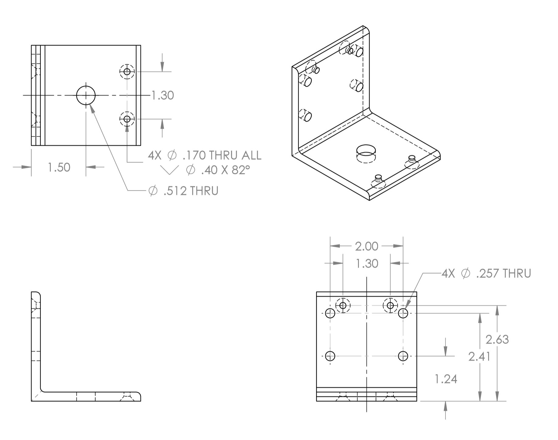
Angle Bracket:
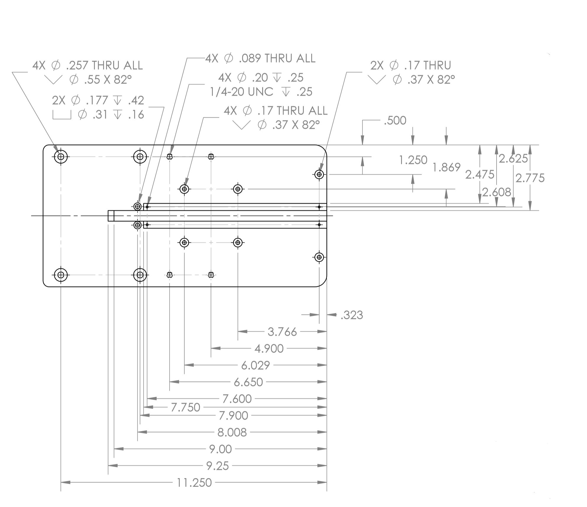
Base Plate:
Rotary Encoder Cover:
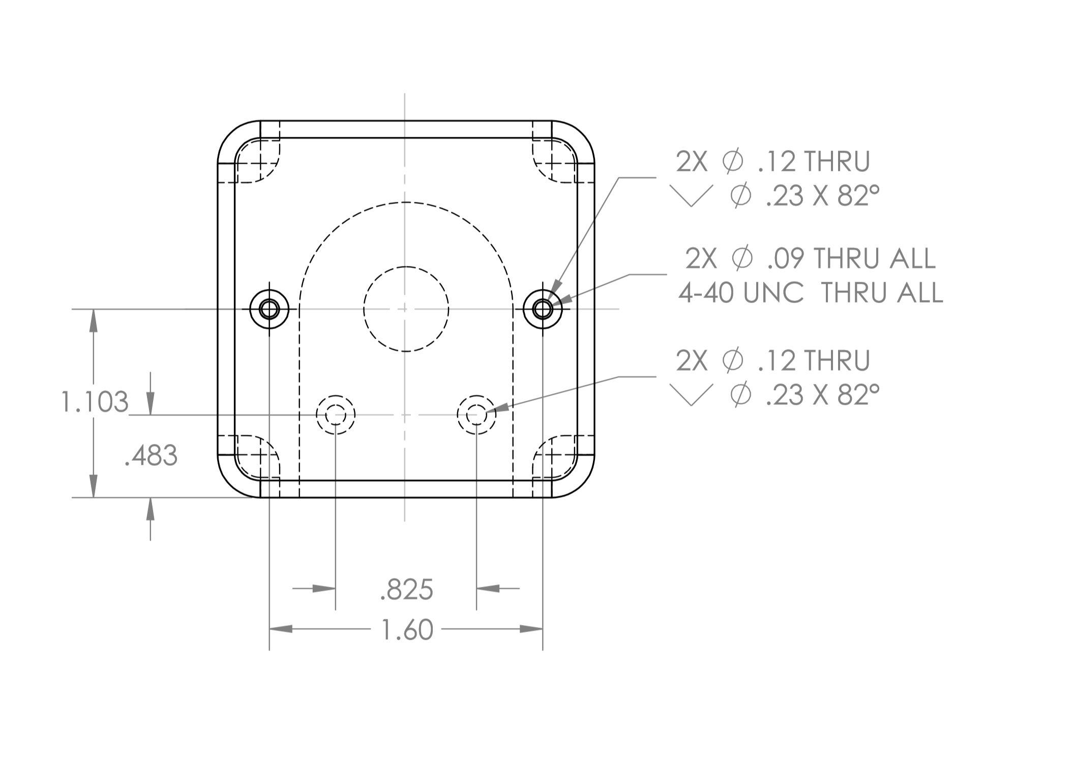
Side Panel:
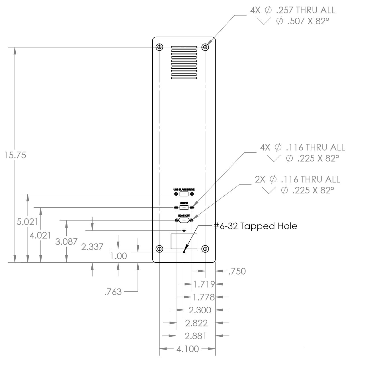
Linear Actuator Mounting Plate:
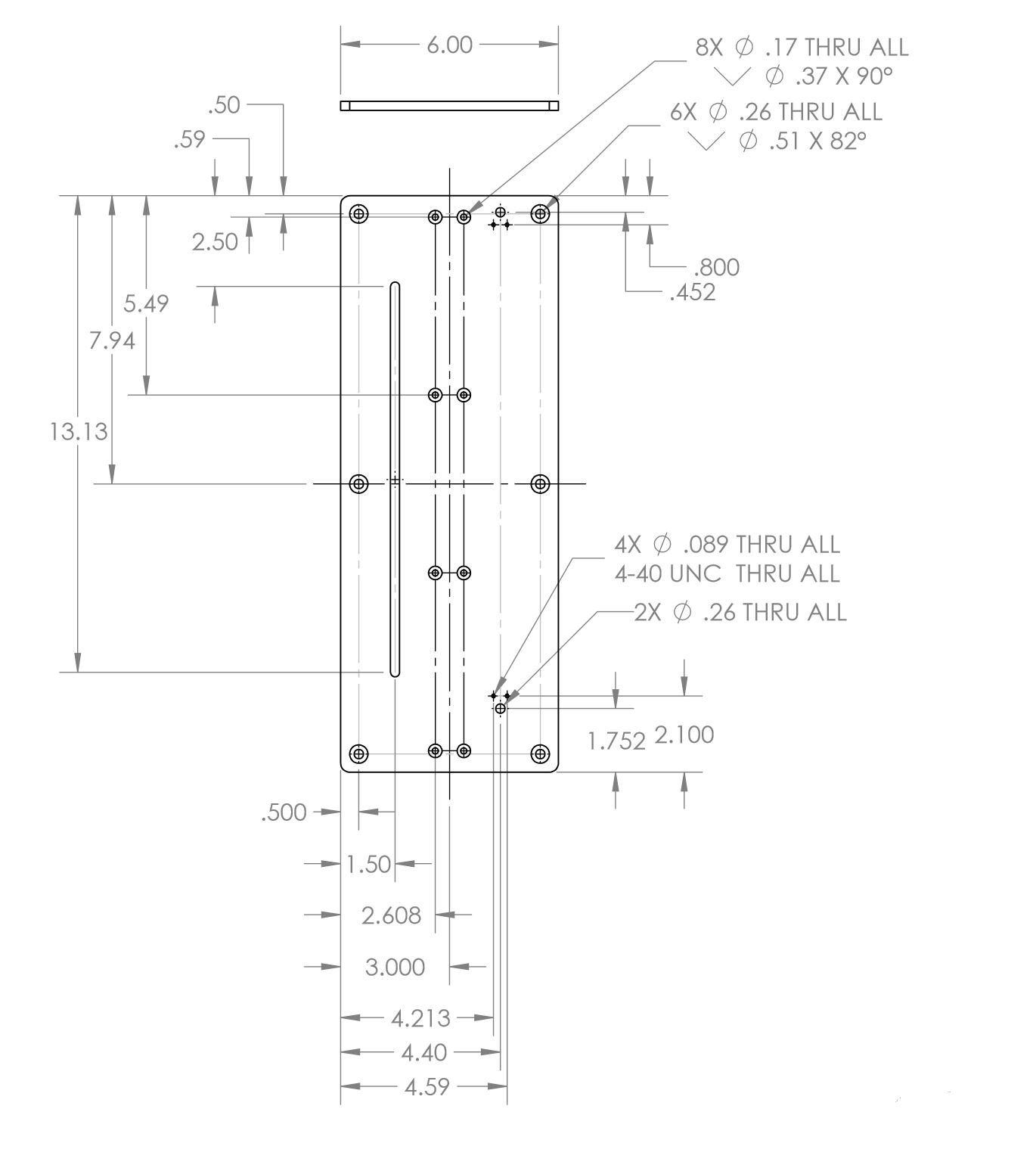
Limit Switch Housing:
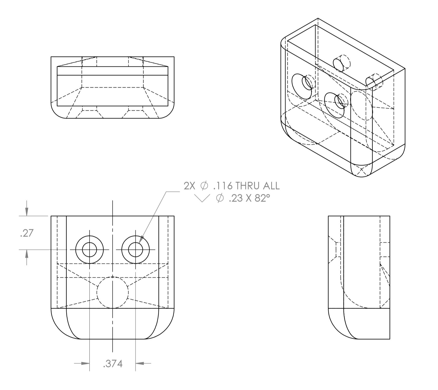
Testing Platform:
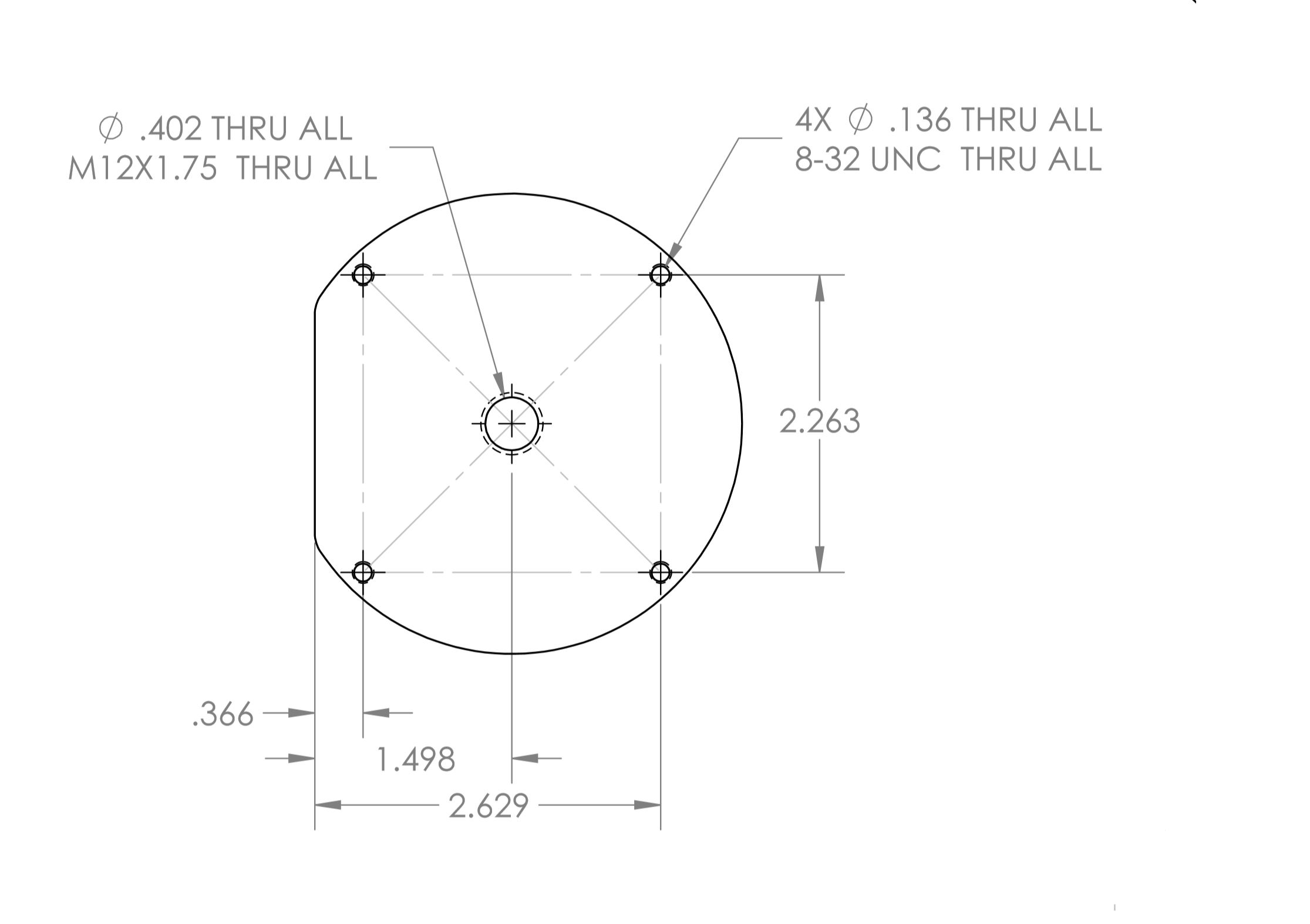
Build
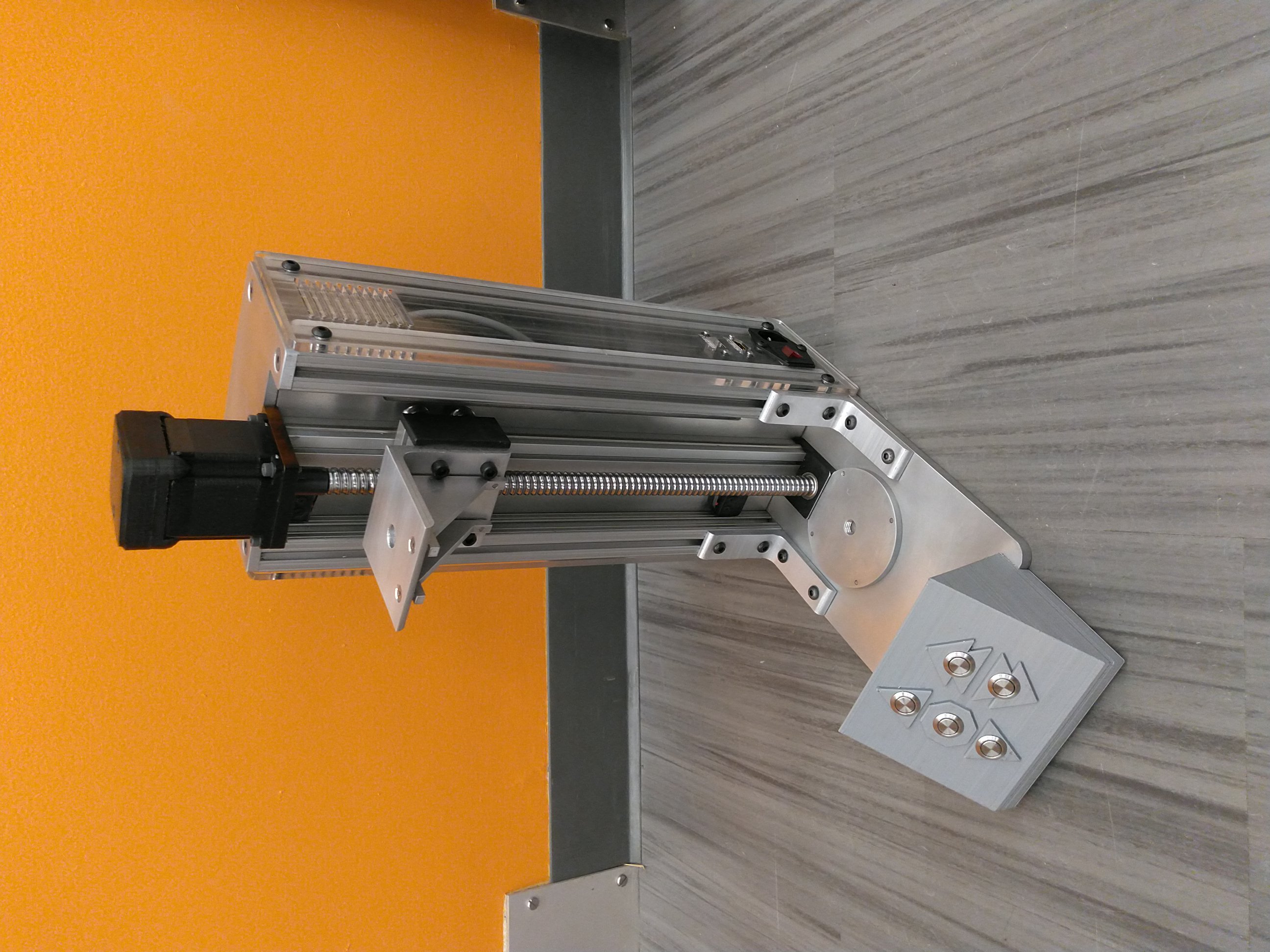
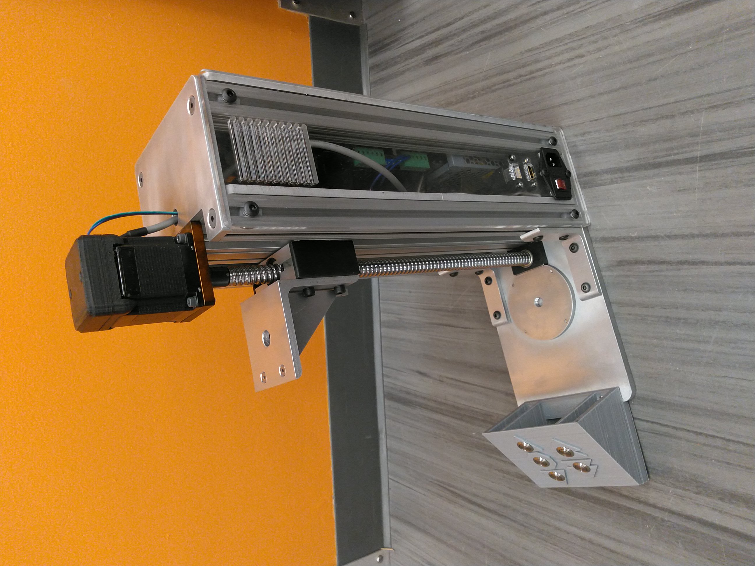
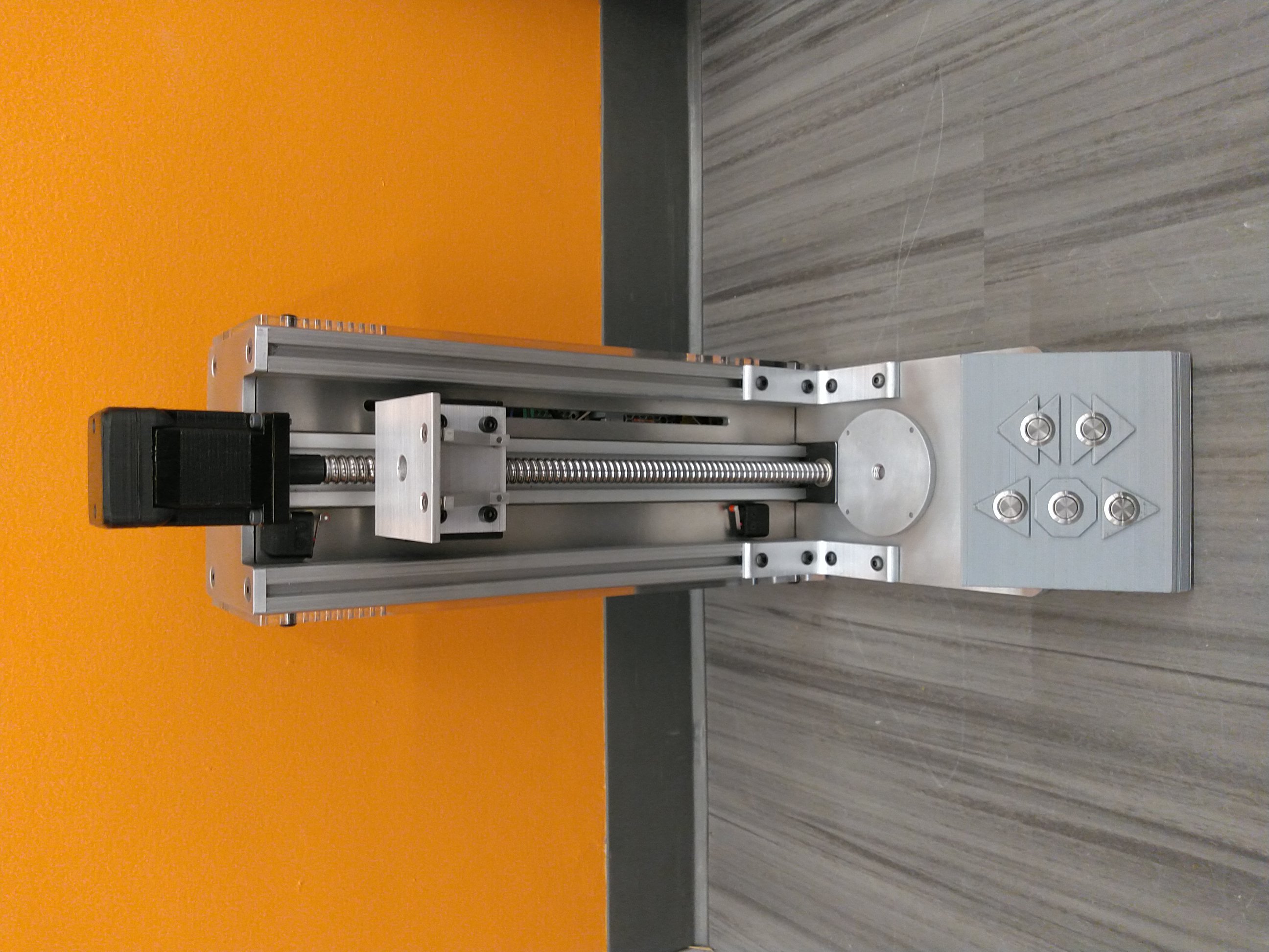
USB Input (for data collection) & HDMI Output (for displaying control interface on a school monitor):
Electronics Mounting Plate:
Buttons for Manual Control:
Code & Graphical User Interface (GUI)
Prototype GUI:
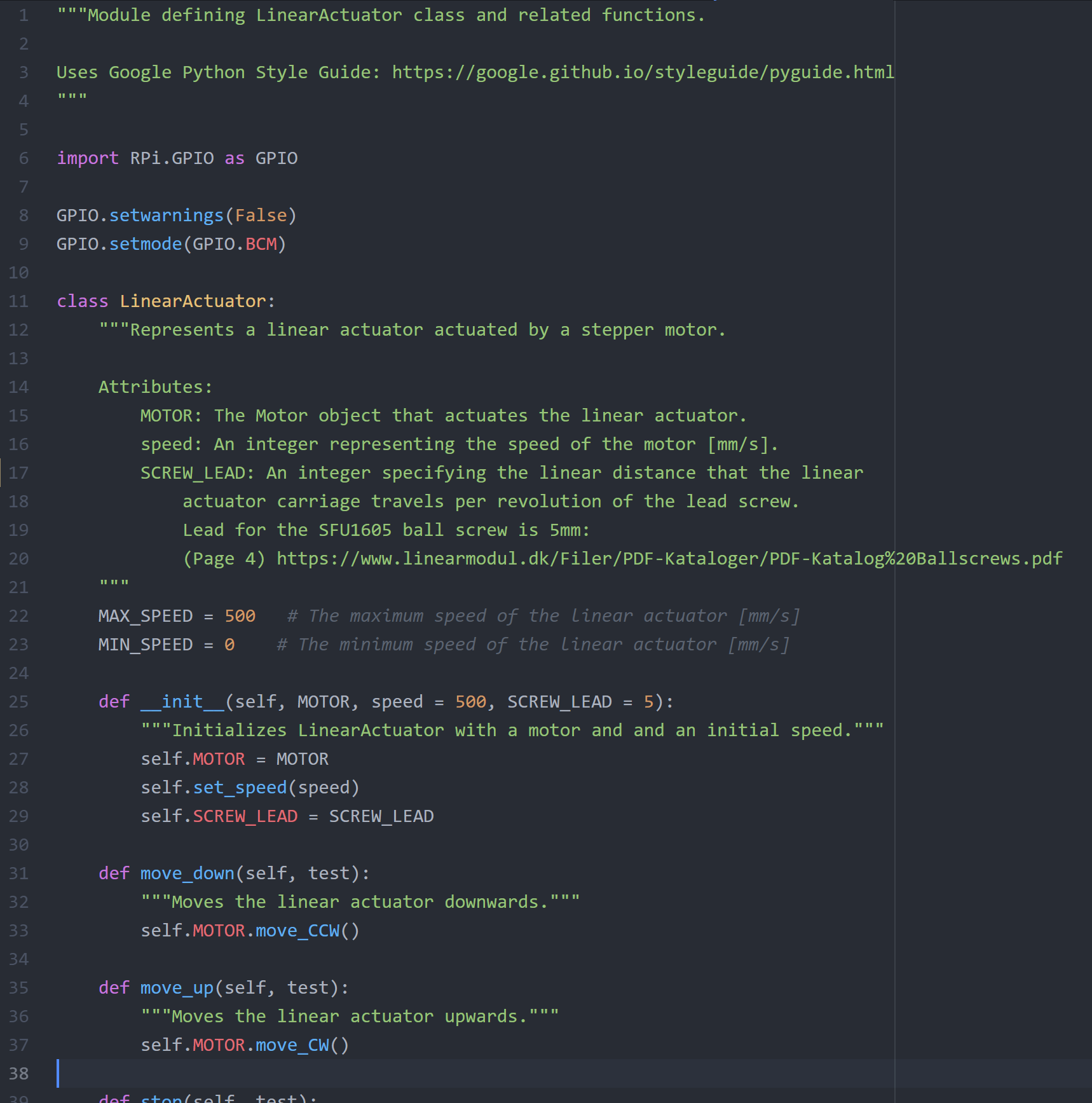
Example Python Class:
Electronics
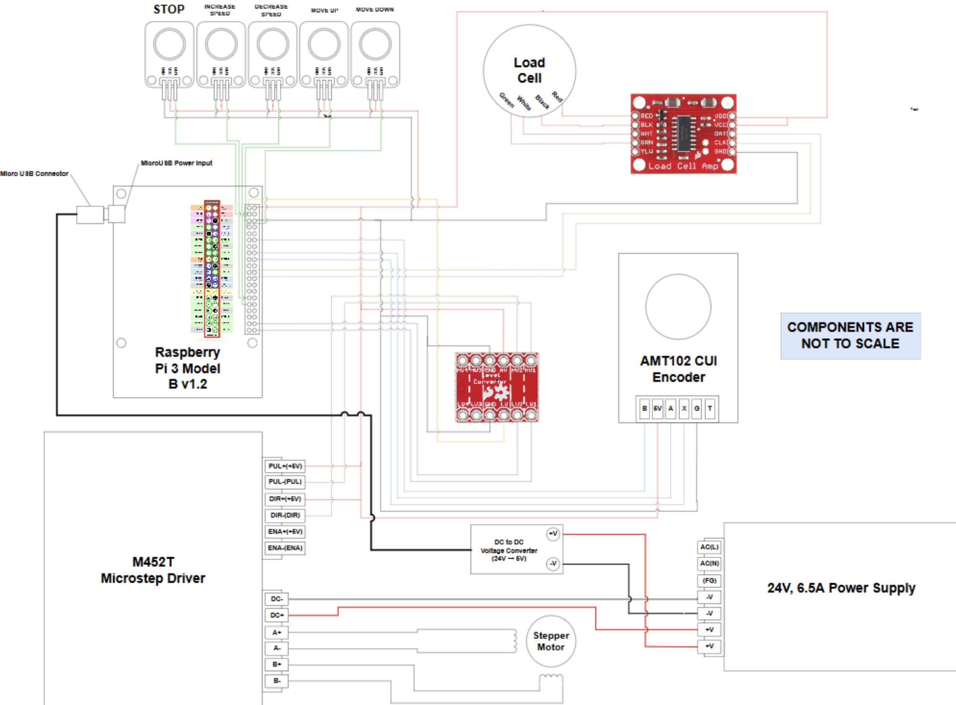
Wiring Diagram:
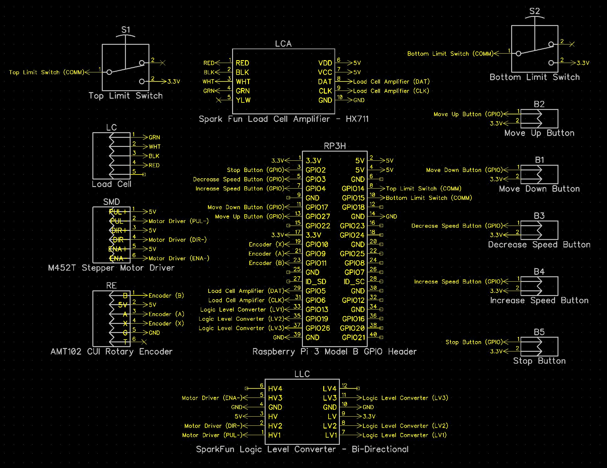
Electrical Schematic:
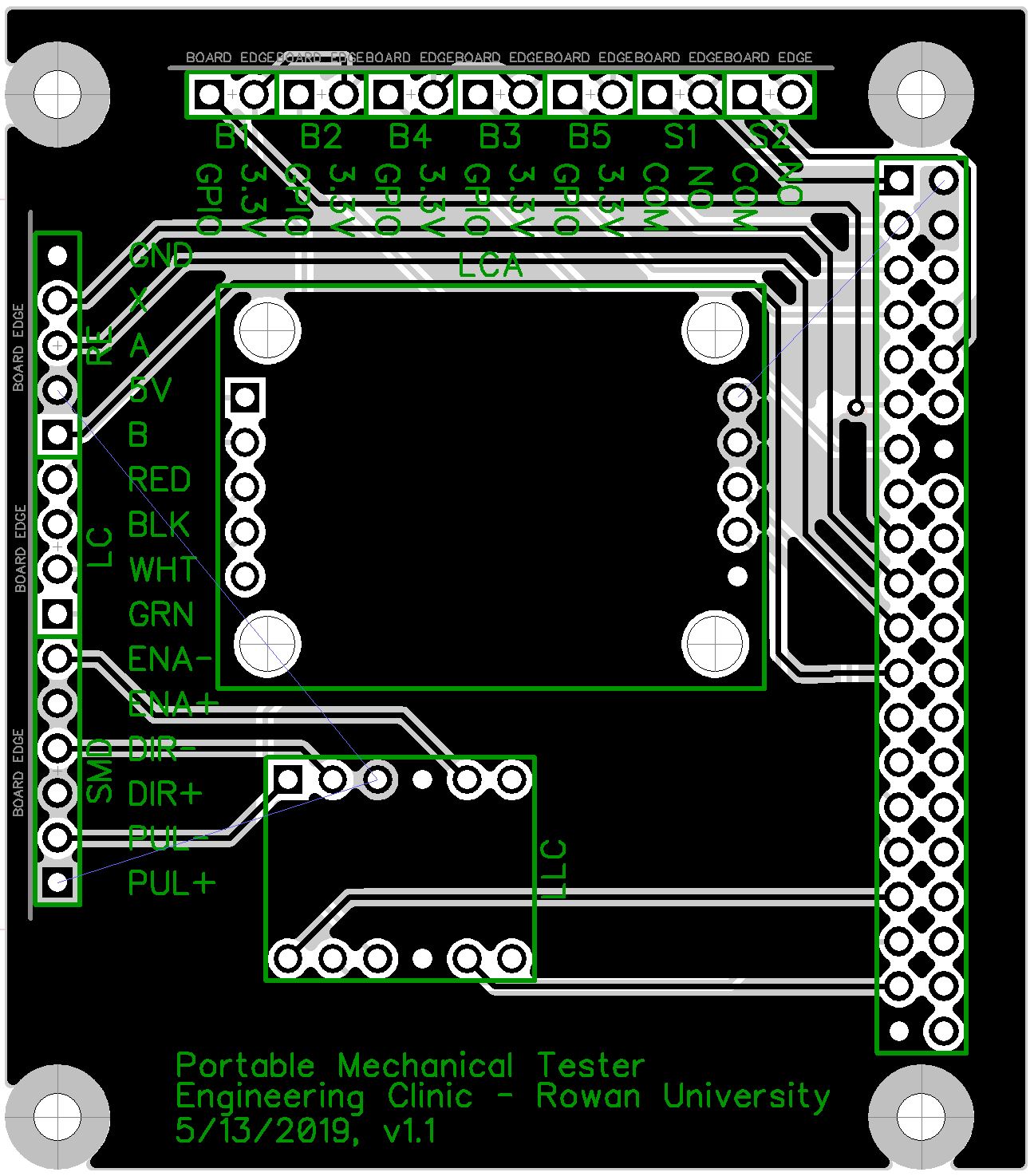
Custom PCB Shield for Raspberry Pi:
Original Tester v.s. New Tester
Original Tester:
New Tester:
